The valve consists of a valve inlet or nozzle mounted on the pressurized system a. Unfortunately to get that one must start at the exit to atmosphere and work backwards to the PSV exit flange.

Safety Valve Installation Spirax Sarco
Typical Open Discharge PSV Connection PSV Reaction force at the point of discharge for Gas Services in lbf F W366 KT K1MAP Here Wflow of any gas or vapor in lbmhr Kratio of specific heats CpCv at the outlet condition Ttemperature at the outlet in Degree R Mmolecular weight of the process fluid.

. The sonic conditions at the outlet will lead to a significant amount of backpressure. Hence design should meet following criteria. Size the relief vent piping system In this paper steps 2 and 3 above are assisted by a design tool SRVQuick which is freeware a beta version of which is available through the IIAR website.
There are three components of inlet losses to the relief valve. PRV discharging Hydrocarbon vapors to atmosphere should be provided with outlet piping at least 3 meters above any equipment within a horizontal distance of 15 meter or 45 meter above the roof of the nearest building whichever is higher. The method of analysis provides a simple technique for determining pressure within a discharge piping system.
Should be limited to 07 and iii density X velocity2 should not exceed 200000. Good Luck Latexman Pats Pubs Proprietor. The PSV discharge piping system should be designed so that the backpressure does not exceed an acceptable value for any pressure-relief device in the system.
Code allows the designer to use the adjusted reduced capacity of the relief valve to size the relief vent. Api recommended practice 520 5th edition part 2 7 and ansi api standard 521 5 provide guidance on the installation and design of the inlet and discharge piping for pressure safety valves. PSV discharge line shall take in to account both the blocked scenario and the fire scenario.
Spring Loaded Design The basic spring loaded pressure relief valve has been developed to meet the need for a simple reliable system actuated device to provide overpressure protection. Of the three sloping the discharge line is the best process design solution but it is also probably the most labour-intensive for fabricationconstruction due to elbow cut-backsnon-parallel butt welds. 20 May 15 1818 Our client is insisting that PSV discharge piping must have the same design pressure as the PSV set pressure of 1200 kPag 175 psig.
The actual stack is suspended from the building structure. Figure 2 is a flowchart for the pressure-relief design procedure. This riser shall be at least 30 meters away from any furnace regardless of the height of riser.
Vent piping o The diameter of the vent pipe must be equal to or greater than the safety valve outlet. Reducer in PSV discharge FSU or FSD. This allows for thermal expansion and ensures that there will be no condensate accumulated in the outlet side.
Normally PSV discharge piping would have lower design pressure since its open pipe to flare ie pressure is limited to backpressure from hydraulic losses in the piping and flare system only. Head Loss in a Pipe Link 45 321. Reducer in PSV discharge FSU or FSD.
This is to avoid noise and too much force in the line while the PSV opens. Fig-ure F2-1 shows the construction of a spring loaded pressure relief valve. Determine Required Capacity Throughout this paper three different relief valve capacities will.
Of 65C for sewer see local Municipal By-Laws Steam A safe point outside the building see below. Typically the discharge piping is fairly short so powerlining line sag between supports is not usually an issue. To learn more about PSV Sizing inlet and discharge PSV piping design enroll in our Piping Systems Mechanical Design and Specification ME-41 Oil Production Processing Facilities PF-4 and Gas Conditioning and Processing G-4.
Require relief devices on the discharge side for deadhead protection. Also note that it is important not to exceed PSV maximum backpressure. The pressure drop should be based on rated capacity of the PSV not the required capacity as pipe will handle a flow corresponding to rated capacity of the PSV when it.
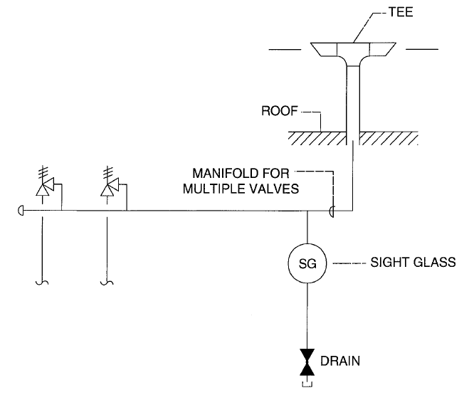
The method is based on adiabatic flow and uses local Mach number to relate expansion of the gas in the pipes to a mass flow function. PSV Inlet and Discharge Piping Another area that requires close attention is the proper design of the inlet and discharge piping of the pressure safety valves. This paper addresses manifolded discharge piping system design.
Apply to Designer Engineer Mechanical Designer and. Proper design of inlet pipe and outlet tail pipe is key for smooth and stable operation of a pressure safety valve psv. A psv at our plant is installed on hydrocarbon service natural gas having set point of 125 psig and is conventional typein existing case this psv discharge pipe height is 6 ft.
Only general guidelines are given however because of widely varying installation requirements. Both at rated conditions as a standard practice Mach velocity shall not be higher than 07. Usually there is an elbow with a condensate pan on it draining to a floor drain.
For PSVs discharging directly to the atmosphere limiting the Mach number to 07 is not practical and a sonic condition could be allowed in the discharge piping. Type of reducers used in PSV discharge Conc. Terminate the discharge pipe not more than 6 inches from the floor in a manner to prevent splashing and scalding of personnel or damage to sewers eg.
Pressure safety valves PSV are used extensively in oil and gas applications to protect vessels pipes and other equipment against overpressure. Not an easy task to do in detail with all the isos or 3D model bits and pieces but not so hard for a first pass with pipe diameters and guesstimated lengths. I have done its dispersion analysis on dnv phast 70 software to check the scenario in case of psv popping than up to what extent the flammable area will be present.
The outlet piping is usually not attached to the valve. Normally PSV discharge piping would have lower design pressure since its open pipe to flare ie pressure is limited to backpressure from hydraulic losses in the piping and flare system only. Additionally the PSV discharge piping design pressure and test pressure.
You can use either a Concentric or Eccentric Reducer in the discharge of a PSV if and only if you are going from the smaller PSV discharge nozzle size to a larger discharge line size to reduce the back pressure. Outlet lines discharging to flare headers are sized to limit the Mach number to 07. Kindra Snow-McGregor Senior Process Consultant and Instructor.
Cp and CvSpecific heat at the constant pressure and at constant volume respectively. Cool to a max. I built-up backpressure should not exceed the overpressure of the PSV in case of conventional type PSV and approximately 50 of total backpressure superimposed plus built-up in case of balanced bellows type ii Mach No.

Piping Engineering How To Design Safety Valve Line Youtube
Modeling Relief Valve Pressure Safety Valve Thrust Force Blog
Atmospheric Termination Of Relief Valve Discharge Piping

The Dos And Don Ts Of Isolating Pressure Relief Valves Valve Magazine

Relief Valve Relief Header Design Oil Gas Process Engineering

Relief Valves For Centrifugal Pumps According To Nfpa 20 Fire Protection Specialists

Water Worker Amtrol 4 4 Gal Water Heater Expansion Tank Water Heater Water Heater Expansion Tank Water Heater Expansion Tanks

How To Size And Select Your Next Pressure Relief Valve
0 comments
Post a Comment